



How to Review a Warehouse Rack-Aisle Lighting Layout Before You Buy
A warehouse aisle can look bright on a rendering and still be difficult to work in. The usual reason is simple: the report proves light on the floor but never proves light on the rack faces where workers read locations, labels, and carton markings.
Before approving a rack-aisle lighting layout, check what was calculated, not just the fixture count and average foot-candles. A useful report should identify the exact luminaire, model the real rack geometry, show minimum as well as average values, and place calculation grids on the surfaces that matter.

1. Start with the work, not a generic target
“Warehouse lighting” is not one visual task. Forklift travel, pallet storage, barcode scanning, case picking, inspection, and packing can occur under the same roof, but they do not necessarily need the same design criteria.
Write down what people must see in each aisle before reviewing any numbers. For example:
- rack location codes viewed from a forklift or order picker;
- small printed labels at lower and upper pick levels;
- pallet edges, rack uprights, floor markings, and pedestrians;
- damaged cartons, spills, or debris on the aisle floor;
- cross-aisle traffic at the end of each rack row.
The owner or design professional should then set the project criteria using the applicable standard, company requirements, and local rules. Do not accept an online “recommended foot-candle” table as the project specification without knowing the task and measurement plane behind it.
2. Verify the geometry in the model
A photometric calculation can be mathematically correct and still describe the wrong building. Compare the report input page with a site drawing or field measurements. At minimum, verify these dimensions:
| Input to verify | Why it changes the result | Evidence to provide |
|---|---|---|
| Mounting height to the fixture | Changes beam spread, intensity, spacing, and glare exposure | Measured height, not nominal roof height |
| Rack height, depth, and row length | Determines shadowing and the vertical surfaces to evaluate | Rack plan plus section or elevation |
| Clear aisle width | Affects fixture location and how much light reaches each rack face | Dimension between loaded rack faces |
| Pallet and carton fill | Loaded racks absorb and block more light than empty frames | Representative photos and reflectance assumption |
| Beams, ducts, sprinklers, conveyors | Can block a fixture even when the top-down plan looks clear | Reflected ceiling plan and site photos |
Also check orientation. In a long rack aisle, a designer may align a linear luminaire with the aisle geometry, but fixture shape alone does not prove the distribution is suitable. The actual photometric distribution and the site model decide the result.
3. Check the floor and rack-face grids
The report should name each calculation plane and its height. For a rack aisle, ask for two different kinds of evidence:
Horizontal aisle grid
This grid evaluates light across the walking or working plane. It should extend along the full aisle and include the spaces between fixtures, the aisle ends, and transition points into cross aisles. A sparse grid placed only under luminaires can hide dark areas.
Vertical rack-face grids
Place vertical calculation grids on both rack faces at the heights where labels or products must be seen. A single point at eye level does not show what happens at the lowest pick slot, at upper levels, or midway between luminaires.
Ask the designer to identify the calculation-point spacing and grid boundaries. The report must make it possible to find the lowest values, not only present a colored rendering.
4. Read averages, minimums, and uniformity together
An average can conceal a poor aisle. A bright area directly below each fixture may pull the average upward while the rack faces between fixtures remain dim.
For every important grid, request at least:
- average illuminance;
- minimum illuminance;
- maximum illuminance;
- the stated uniformity ratio and its direction, such as average-to-minimum or maximum-to-minimum;
- the calculation plane height and point spacing.
Never compare two ratios until you confirm that they use the same definition. A lower average-to-minimum ratio generally indicates a more even grid, but it does not rescue a plan whose minimum is below the project criterion. Conversely, a sufficient minimum does not automatically address glare or excess power.
5. Confirm the exact fixture and photometric file
A photometric plan is tied to the luminaire data used in the calculation. Match the report’s manufacturer, model, wattage setting, CCT option, optic or beam distribution, and IES filename to the exact product proposed on the quote and submittal.
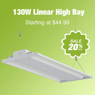
This matters when one product family contains several wattages or selectable configurations. YXL’s current linear high bay collection, for example, contains multiple product families and settings. Do not assume that an IES file from one variant represents every other variant in the collection.
For any shortlisted YXL model, review the live product specifications and its DOWNLOAD documents before approval. The current Basic Series linear high bay page lists several wattage variants and links its product manual. The final layout should identify the specific configuration used—not simply “linear high bay.”
6. Review the parts a clean rendering tends to omit
Now compare the calculation with the operating warehouse. Mark each item as modeled, addressed by placement, or still unresolved:
- Stored goods: Were racks modeled as solid or reflective surfaces, or left empty?
- Structural conflicts: Are joists, sprinkler mains, ducts, cranes, or cable trays between the fixture and the aisle?
- Fixture offset: If a fixture cannot sit on the aisle centerline, was the actual offset recalculated?
- Glare: Will operators look toward bright luminaires while raising a mast, scanning upper levels, or turning into a cross aisle?
- Controls: Are sensors divided by aisle, or can motion in one area leave an occupied aisle dim?
- Future rack changes: Will planned row extensions or re-slotting move racks beneath the light path?
- Emergency lighting: Is it handled in the project documents rather than assumed from the normal-lighting calculation?
If the ceiling plan changes after the lighting layout is finished, revise the calculation before ordering. Moving several fixtures around an obstruction can create a different result even when the fixture count stays the same.
7. Turn the layout into an acceptance plan
A report is most useful when it defines what will be checked after installation. Before issuing the purchase order, agree on:
- the exact fixture schedule and field-selectable settings;
- the calculation planes and project criteria;
- where field measurements will be taken;
- whether measurements occur with representative racks loaded;
- sensor time delay, high level, low level, and aisle zoning;
- who can approve a fixture relocation or setting change;
- how any difference between predicted and measured performance will be resolved.
Field measurements will not exactly duplicate a computer model because real reflectances, voltage, temperature, dirt, and inventory differ from assumptions. The goal is not to demand identical point-by-point values. It is to confirm that the installed system meets the agreed criteria in the places where work is performed.
One-page approval worksheet
| Approval question | Pass evidence | Status |
|---|---|---|
| Does the model match current racks and mounting heights? | Dimensioned plan and section match field measurements | Pass / Revise |
| Are floor and both rack faces calculated? | Named horizontal and vertical grids are included | Pass / Revise |
| Can the lowest-performing points be found? | Average, minimum, maximum, ratio, and point values are shown | Pass / Revise |
| Does the report use the quoted configuration? | Model, wattage setting, CCT, optic, and IES filename match | Pass / Revise |
| Are obstructions and controls resolved? | Coordinated ceiling plan and control narrative are attached | Pass / Revise |
| Is post-installation verification defined? | Measurement locations, settings, reviewer, and remedy are agreed | Pass / Revise |
A rack-aisle layout is ready to approve when the geometry, task planes, lowest values, exact fixture data, obstructions, and commissioning method all agree. If any one of those is missing, request a revision before equipment is ordered.
If you are planning a YXL high bay project, send the rack plan, mounting heights, aisle dimensions, operating tasks, ceiling obstructions, voltage, and control requirements with your lighting-layout request. That information gives the designer a defensible starting point and reduces revisions later.
Electrical installation, emergency-lighting design, and code compliance must be reviewed by qualified professionals for the specific project and jurisdiction.
Sample Image Gallery


