



What to Mark on a Warehouse Ceiling Plan Before a High Bay Layout
A warehouse floor plan is not a lighting plan until the ceiling is documented. Ducts can block distribution, cranes can move through a proposed fixture row, skylights can change daytime conditions, and a mounting point that looks clear on paper may be unreachable from the floor.
Before requesting a high-bay layout, mark each fixed obstruction, moving obstruction, mounting constraint, and service-access constraint on one coordinated drawing. The goal is not to make the plan look busy. It is to prevent a photometric calculation from modeling fixtures where they cannot work or cannot be maintained.
Start with four transparent layers
Use the architectural or rack plan as the base. Add four separate overlays so each trade can revise its own information without redrawing the entire warehouse.

Four coordination layers on an illustrative ceiling plan. Verify every field condition and required clearance for the actual project.
| Layer | Mark these items | Why they matter |
|---|---|---|
| Fixed overhead | Ducts, beams, cable trays, pipes, fans, mezzanines, overhead doors | They can block distribution or eliminate a mounting location. |
| Life safety | Sprinklers, detectors, alarms, fire doors, exit signs, emergency lighting | Lighting must be coordinated without impairing required systems. |
| Moving envelope | Crane bridges, hoists, doors, lifts, conveyors, maximum load height | The whole swept path matters, not only the parked position. |
| Access and change | Lift routes, restricted zones, production equipment, future racks | A fixture that cannot be reached becomes a maintenance problem. |
Do not use this map to guess code clearances. It records existing conditions and known constraints. Required separation, support, wiring, and fire-protection coordination belong to the responsible qualified professionals and the authority having jurisdiction.
Turn “near aisle four” into usable dimensions
A ceiling photo adds context, but the designer still needs a coordinate. Give every important object a plan location and an elevation.
- X and Y position: Measure from a fixed grid line, column, or wall—not a pallet that may move tomorrow.
- Lowest elevation: Record the lowest point above finished floor.
- Outside envelope: Include insulation, brackets, motors, guards, and other projections.
- Mounting structure: Show where attachment is actually available.
- Status and owner: Note existing, remain, relocate, future, or unknown, plus the trade responsible.
Ceiling height and fixture mounting height are not interchangeable. A 30-foot roof deck does not create a 30-foot mounting height when the fixture must hang below trusses or clear a duct bank.
Use one record card per important obstruction

Give each obstruction a measurable location, an elevation, and an owner. This blank card is a field tool, not a code-clearance schedule.
Give the obstruction an ID that appears on the drawing, the photo, and the schedule. A busy facility team should not have to guess whether “duct photo 7” is above receiving or packing.
| Field | What to enter |
|---|---|
| ID and object | A unique label and plain description |
| Plan location | Grid or column references and outside limits |
| Elevation and size | Lowest point and full outside envelope |
| Owner and status | Responsible trade; remain, relocate, future, or unknown |
| Consequence | Keep-out, blocks light, or limits access |
Label what happens if the object is ignored
Not every pipe deserves the same response. Use three consequence labels:
- Hard keep-out: No fixture, support, cord, or service activity may occupy the defined envelope. Record who established it.
- Photometric obstruction: A fixture may physically fit, but the object can create a repeatable shadow on a work surface.
- Access constraint: The location may light well when new, but inspection, cleaning, controls adjustment, or replacement would be difficult.
This is where many drawings become easier to review: a narrow conduit and a five-foot duct bank stop being treated as the same problem.
Draw the moving envelope, not the parked machine
A moving obstruction cannot be represented by one rectangle at rest. For cranes and hoists, use the manufacturer's dimensions and the facility's operating limits. For overhead doors, show the hardware in the fully open position. For lifts and tall loads, document the maximum approved travel or storage height.
The lighting review should consider at least two states: equipment parked and equipment in its most obstructive normal operating position. If a task surface becomes dark only when the crane is centered over it, an average floor value may hide the problem.
A quick coordinate test can expose a bad row
Assume a proposed fixture row runs east–west at Y = 40 ft. A duct bank follows the same line from X = 30 ft to X = 90 ft. Its bottom is 24 ft 6 in above finished floor. The roof deck is 30 ft, and the preliminary layout assumed fixtures at 28 ft.
The map now forces three useful questions:
- Can the fixtures and supports physically occupy that row?
- Would shifting the row preserve light on the actual task surfaces?
- Would the revised positions remain reachable by the approved lift route?
Do not answer with a generic spacing chart. Model the approved candidate positions using the exact luminaire photometric file and the actual mounting height. In fixed-rack areas, evaluate aisle and vertical-task geometry rather than relying only on a whole-room average.
What the lighting designer should receive
Send one controlled package, not six email threads:
- a dimensioned plan with scale and stable grid references;
- rack footprints, heights, aisle widths, task locations, and future phases;
- ceiling structure and usable mounting points;
- all four obstruction layers and the obstruction schedule;
- work zones, daylight openings, operating schedule, and control intent;
- existing electrical information for verification by the project electrician;
- maintenance method, lift routes, and restricted-access areas;
- photos keyed to plan coordinates.
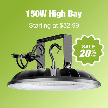
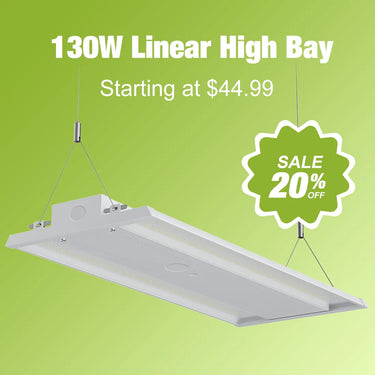
If a YXL fixture is being considered, attach the exact proposed configuration and current documents from its DOWNLOAD section. The YXL high-bay family includes multiple choices, so “use the high bay from the website” is not enough for a final model.
Send the package for a project-specific YXL lighting layout review. The designer can then test position, distribution, mounting height, and task-plane results against the actual building—not the cleaner building everyone wishes they had.
One last walk: Follow the proposed rows while looking up, then walk them again while thinking about service access. If the drawing and the ceiling disagree, the ceiling wins.
Sample Image Gallery


